Headlines
View MoreReasearch Progress
View More-
 03 Sep,2024
Research Progress on Effects of wall temperature on hypersonic shock wave/turbulent boundary layer interactions
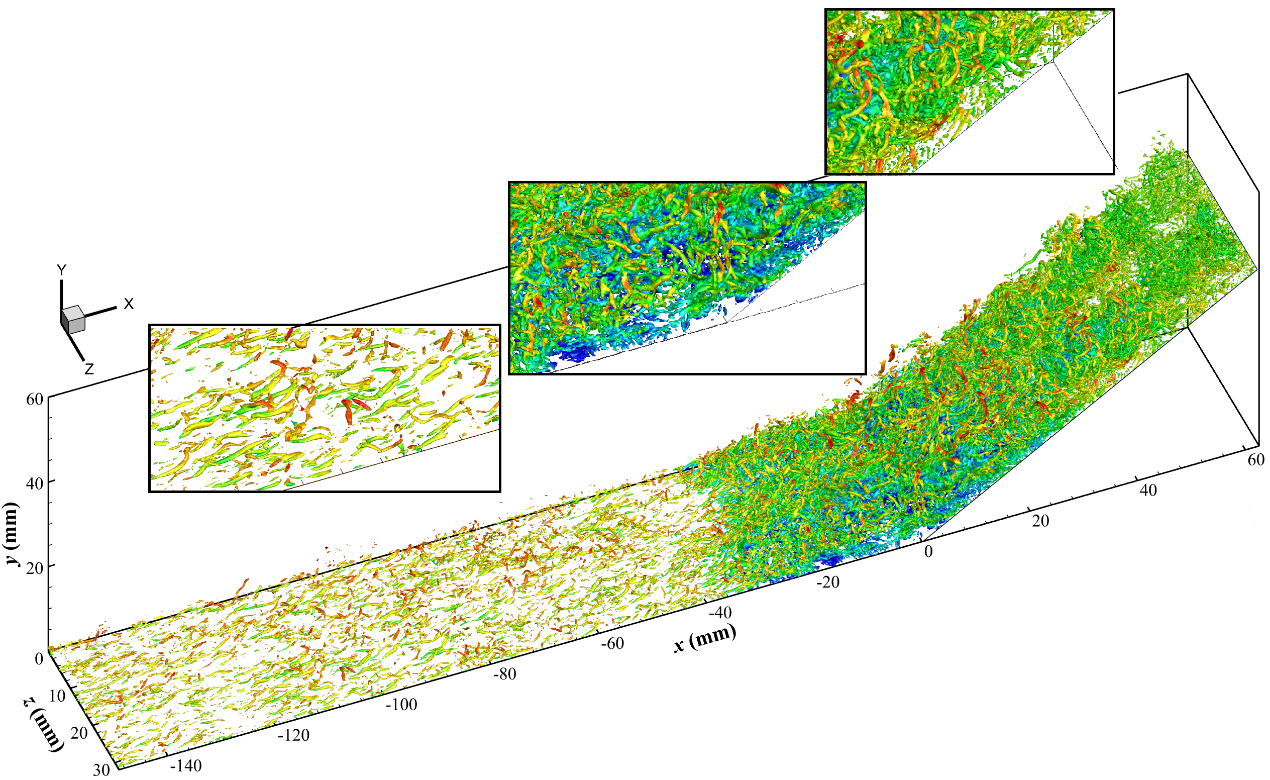
Shock wave/turbulent boundary layer interactions (STBLIs) commonly occur in the internal or external flow of supersonic or hypersonic vehicles and have an important influence on aerodynamic characteristics. Wall temperature has become a research emphasis because of its significant effects on compressible boundary layers and STBLIs. Recently, the research team led by Prof. Li Xinliang from the Institute of Mechanics, Chinese Academy of Sciences, conducted direct numerical simulations (DNSs) to investigate the wall temperature effects on hypersonic STBLIs. This research focused on elucidating the mechanisms of wall temperature effects on the flow structures and low-frequency unsteadiness, and derived an equation to predict the wall pressure distribution at different wall temperatures. The work, titled "Effects of wall temperature on hypersonic shock wave/turbulent boundary layer interactions," has been published in the Journal of Fluid Mechanics, with authors including Zhang Ji, Guo Tongbiao, Dang Guanlin, and Li Xinliang.In this research, the heterogeneous parallel finite difference solver OpenCFD-SCU is adopted for the DNSs of STBLIs over a 34° compression ramp at Mach number 6. Three values of the wall-to-recovery-temperature ratio (0.50, 0.75, and 1.0) are considered in the simulations. Figure 1 shows a numerical result (Iso-surfaces of Q with the adiabatic wall) with high spatiotemporal resolution. The research indicates that cooling the wall can reduce the size of the separation bubble, as shown in figure 2. This is because a colder wall contributes to fuller profiles of density and velocity in the turbulent boundary layer, leading to a greater momentum of the near-wall fluid to resist the separation.Figure 1. Iso-surfaces of instantaneous Q = 0.1 coloured by the streamwise velocity in the cases of .Figure 2. Contours of the mean streamwise velocity and streamlines in the x-y plane in the cases of (a) , (b) , and (c) .According to the FIT and the simulation data, the following equation is proposed to describe the wall pressure rise process upstream from the corner when the wall temperature changes:where n is close to 0.85 in the compression ramp STBLIs. Figure 3 shows that the results predicted by this equation are generally consistent with those of the simulations.Figure 3. Prediction results of the mean wall pressure at (a) M∞ = 2.9 and (b) M∞ = 6.0.The analysis based on the weighted power spectral density (WPSD) indicates that cooling the wall can significantly suppress the low-frequency unsteadiness by reducing the energy of the low-frequency motion and narrowing its streamwise range, as shown in figure 4. The analysis of the correlation between the upstream and downstream flows indicates that the low-frequency unsteadiness is mainly driven by the downstream mechanism. Therefore, the suppressed low-frequency unsteadiness is caused by the decreasing size of the separation bubble when the wall temperature decreases.Figure 4. Contours of the wall pressure WPSD in the cases of (a) , (b) , and (c) .Link to the paper:https://doi.org/10.1017/jfm.2024.533
-
 24 Jun,2024
New strategy to obtain carbon nanotube fibers with ultrahigh dynamic strength
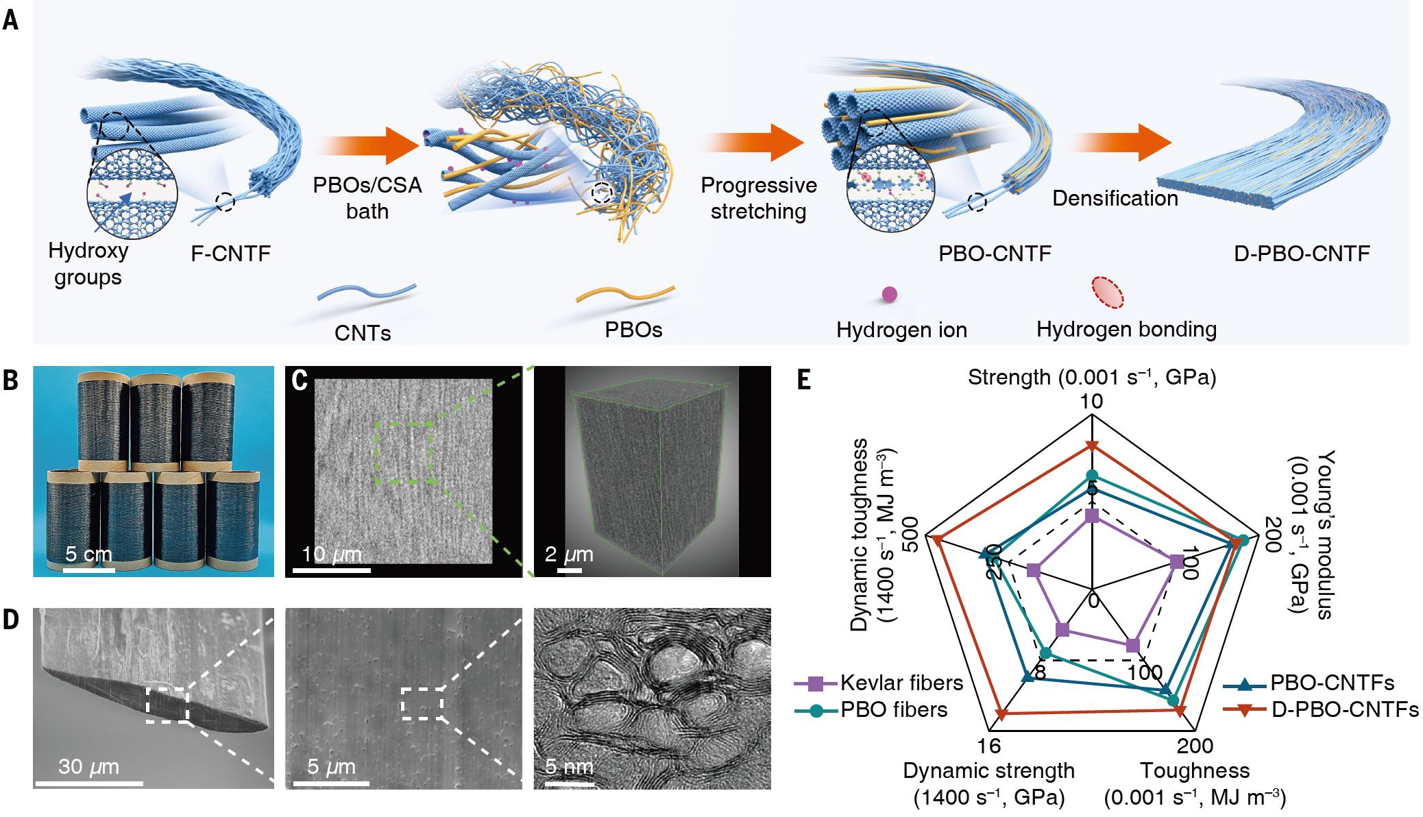
Prof . ZHANG Jin and A . P . JIAN Muqiang from Peking University and the Beijing Graphene Institute , Prof . WU Xianqian from the Institute of Mechanics , Chinese Academy of Sciences , P . GAO Enlai from Wuhan University .Chinese Academy of Sciences and their teams ? developed a strategy to fabricate carbon nanotube fibers with the dynamic strength up to 14 GPa . This work has been published in Science with the title of “ Carbon nanotube fibers with dynamic strength up to 14 GPa . ” on June.Prof. ZHANG Jin and Assoc. Prof. JIAN Muqiang from Peking University and the Beijing Graphene Institute, Prof. WU Xianqian from the Institute of Mechanics, Chinese Academy of Sciences, Assoc. Prof. GAO Enlai from Wuhan University, Prof. ZHANG Yongyi from the Suzhou Institute of Nano-Tech and Nano-Bionics, Chinese Academy of Sciences and collaborators developed a strategy to fabricate carbon nanotube fibers with dynamic strength up to 14 GPa. This work has been published in Science with the title of “Carbon nanotube fibers with dynamic strength up to 14 GPa” on June 21.High-performance fibers with lightweight, high dynamic strength and excellent energy absorption capability are persistently required for high-strain-rate application scenarios such as battlefield protection and space debris capture. Carbon nanotubes that possess excellent properties including lightweight, strong, high modulus, highly electrical and thermally conductive are considered as one of ideal building blocks for the next generation of high-performance fibers, promising to meet the needs of high-strain-rate applications. However, due to the issues of fiber assembly structure, the tensile strength of carbon nanotube fibers remains below 10 GPa, far below their ideal strength, indicating substantial room for improvement.They therefore proposed an innovative multi-scale structural optimization strategy to systematically optimize the interfacial interactions, nanotube alignment, and densification of carbon nanotube fibers. This has resulted in dynamic strength reaching up to 14 GPa, breaking the existing strength record for fibers. Firstly, the carbon nanotube fibers produced by floating catalyst chemical vapor deposition were purified and functionalized. Then, the fibers were subjected to progressive stretching in a chlorosulfonic acid (CSA) solution containing poly(p-phenylene-2,6-benzobisoxazole) (PBO), followed by mechanical densification. This strategy leads to improvements in interfacial interactions, nanotube alignment, and densification within the fibers. (Fig. 1), achieving a breakthrough in both quasi-static and dynamic strength.Fig. 1. Preparation, morphology, and mechanical properties of CNTFs. (A) Strategy to develop highly packed and well-aligned CNTFs. (B) Digital photograph of PBO-CNTF tows. (C) Three-dimensionally reconstructed void microstructure (right) derived from nano-CT results (left) for D-PBO-CNTFs. (D) SEM (left and middle) and TEM (right) images of the radial cross section of D-PBO-CNTF cut by a focused ion beam. (E) Radar chart for comparing the mechanical performance of different CNTFs and commercial fibers (PBO and Kevlar 29 fibers). (Image by PKU, BGI, IMECH, WHU and SINANO)The ordered assembly of carbon nanotubes endows the fibers with excellent mechanical properties. The quasi-static strength of the carbon nanotube fibers reaches 8.2 GPa, and the Cunniff velocity that used to evaluate its ballistic performance exceeds 1100 m/s (Fig. 2A-C). To disclose the impact protection performance of the carbon nanotube fibers, a mini-split Hopkinson tension bar was employed to measure the mechanical behavior of the fibers under high-strain-rate loading. The results indicated that as the tensile rate increased, the fibers experienced a transition from ductile to brittle failure behavior, rendering the fibers significant strain-rate-strengthening effects. When the strain rate was approximately 1400 s–1, the dynamic strength of the fibers reached up to 14 GPa, surpassing all other high-performance fibers (Fig. 2D-G). Furthermore, a laser-induced high-velocity transverse-impact testing was built to investigate the dynamic response of the fibers under simulated ballistic impact loading. The result showed that the specific energy dissipation power of the fibers reached (8.7 ± 1.0) × 1013 m kg–1 s–1, far exceeding that of traditional bulletproof fibers such as Kevlar (Fig. 2H-I). These results indicate that carbon nanotube fibers have great potential for application in impact protective engineering.Fig. 2. Mechanical properties of CNTFs. (A) Quasi-static stress-strain curves of F-CNTFs, CSA-CNTFs, PBO-CNTFs, and D-PBO-CNTFs. (B) Comparison of quasi-static tensile strength, Young’s modulus, and toughness of different CNTFs. (C) Comparison of specific energy absorption and longitudinal wave velocity of our fibers (indicated by stars) and other high-performance fibers. (D) Stress-strain curves of F-CNTFs, CSA-CNTFs, PBO-CNTFs, and D-PBO-CNTFs at high strain rates of about 1400 s–1. (E) Comparison of the strength of CNTFs at different strain rates. Error bars indicate the standard deviation of the means of independent measurements. (F) Comparison of the dynamic strength of our fibers and other high-performance fibers at high strain rates. (G) Comparison of the dynamic toughness of CNTFs at different strain rates. Error bars indicate the standard deviation of the means of independent measurements. (H) Schematic diagram of laser-induced high-velocity transverse impact on a single fiber. Here, PDMS, v, Δt, and γ represent polydimethylsiloxane, impact velocity, interval time, and deflection angle, respectively. (I) SEDP values of different fibers. Error bars indicate the standard deviation. (Image by PKU, BGI, IMECH, WHU and SINANO)The synergistic enhancement of interfacial interactions, nanotube alignment, and densification of carbon nanotube fibers is crucial for their excellent mechanical properties. In-situ Raman testing and molecular dynamics simulations indicated that strong interactions between PBO and carbon nanotubes enhance intertube interactions and stress transfer (Fig. 3A and B). Coarse-grained simulation results suggested that during progressive stretching, the addition of PBO reduces fiber porosity, increases density, and decreases stress concentration (Fig. 3C). Under high-speed loading conditions, a higher proportion of carbon nanotubes in the fibers break, and the fiber fracture mode transitions from intertube sliding to more synchronous carbon nanotube fractures (Fig. 3D-G), thereby endowing the fibers with superior dynamic mechanical properties.Fig. 3. Mechanistic analyses of the dynamic performance of CNTFs. (A) Dependence of Raman frequency downshifts on the applied strains for F-CNTFs and PBO-CNTFs. (B) Stress-relaxation curves of different fibers at 1.5% strain. (C) Simulation snapshots of progressive stretching treatment for CNTFs with and without PBO. (D) Structures and cross-sectional morphology of the simulated model. (E) Snapshots of deformed D-PBO-CNTFs under low (left) and high (right) loading velocities. The atoms are colored according to the bond strain. (F) Stress-strain curves of CSA-CNTFs and D-PBO-CNTFs under low and high loading velocities. (G) Percentage of broken CNTs for CSA-CNTFs and D-PBO-CNTFs during the tensile process, which is counted up to the peak stress in the stress-strain curves. (Image by PKU, BGI, IMECH, WHU and SINANO)Carbon nanotube fibers, characterized by their extremely high dynamic strength, hold significant potential for applications in aerospace and impact protection. Their work provides a feasible route to harness the intrinsic strength of individual CNTs at the macroscale to fabricate impact-resistant fibrous materials.Contact:CHEN YuyingInstitute of Mechanics Chinese Academy of Sciences Chinese Academy of SciencesTel: 86-10-82544075E-mail: chenyuying@imech.ac.cnWeb: http://english.imech.cas.cn/
-
 04 Mar,2024
Researchers further reveal shielding effect of double edge cracks
The edge crack problem is often observed in engineering applications. It is one of the most prominent factors causing damage and failure of engineering structures, and it is also one of the classical problems in fracture mechanics. Due to the structure heterigenety and the loading conditions complexity, multiple cracks often occur on the edge. The interaction between cracks will affect the crack propagation path and the failure mode of the structure. To study the mechanical properties of multiple edge cracks under different loading conditions is of great engineering significance. Engineers can rationally use the interaction between cracks to improve the life of structures under specific working conditions.
The edge crack problem is often observed in engineering applications. It is one of the most prominent factors causing damage and failure of engineering structures, and it is also one of the classical problems in fracture mechanics. Due to the structure heterigenety and the loading conditions complexity, multiple cracks often occur on the edge. The interaction between cracks will affect the crack propagation path and the failure mode of the structure. To study the mechanical properties of multiple edge cracks under different loading conditions is of great engineering significance. Engineers can rationally use the interaction between cracks to improve the life of structures under specific working conditions.
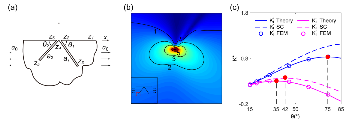
The research team of the State Key Laboratory of Nonlinear Mechanics, Institute of Mechanics, Chinese Academy of Sciences constructed the boundary value problems combining conformal mapping and plane elasticity theory. The complex function is solved by a semi-analytic method, and the corresponding mechanical parameters are calculated. The research team mainly studied double branched cracks (two cracks emanating at the same point at the edge) and Kalthoff-Winkler cracks (two spaced cracks) under far-field uniform tension or concentrated force loading at the boundary. The stress intensity factors, elastic stress fields, and crack opening displacement are calculated. The shielding effect between cracks is investigated. Compared with a single edge crack, the stress intensity factors of a double branched crack decrease due to the shielding effect. The SIFs decay exponentially with decreasing space between the two parallel cracks. KI=KI0-KI1-exp(-a/d)](Fig 1 and 2). The method is universal to study boundary crack problems, and the shielding effect of cracks plays a guiding role in engineering applications.
The above results have been published under the title “Elastic fields of double branched and Kalthoff-Winkler cracks in a half-plane” in the Journal of the Mechanics and Physics of Solids. The first author is doctoral student Yangjian Si. This work is supported by the NSFC Basic Science Center for ‘Multiscale Problems in Nonlinear Mechanics’ (No.11988102).
Fig 1: Normalized SIFs and stress fields of a symmetric double-branched edge crack (a1=a2,?θ1=θ2) subjected to far-field unform tension.
(a) Geometry and loading condition of the crack. (b) Von Mises stress field around the crack tip. (c) Normalized SIFs as a function of θ. Shielding effect between the two branches can be clearly observed.
Fig 2:Normalized SIFs of two parallel edge cracks (following Kalthoff-Winkler experiment) under far-field uniform tension.
(a) Geometry and loading condition of the crack. (b) Normalized SIFs as a function of a/θ. KI*=1.122-0.326[1-exp(-1.8a/d)] ,KII*=0.812[1-exp(-1.2a/d)]. The normalized SIFs converge to those of a single edge crack when d approaches to infinity.
Upcoming Events
View More-
07
Apr,2025The 1st International Symposium on Non-equilibrium Transport Phenomena
-
28
Nov,2024Recent advances of numerical modelling of coastal engineering problems: breaking waves and sediment transport
-
19
Nov,2024Accelerating energy transition with high-performance computing of multi- phase, reacting thermo-fluid systems
-
19
Nov,2024Modeling of reservoir applications relevant to CO2 sequestration portfolio
-
08
Nov,2024All defects are equal, but some are more equal than others: A disordered story
-
05
Nov,2024Osseointegration of nanoTi and nanoMg implants
IMECH in Media
View More-
 02 Aug,2023
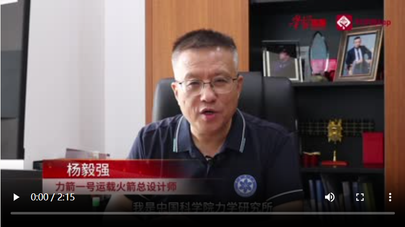
【Science News】Scientists Answer Letters | Yang Yiqiang: What's so great about China's most powerful solid rocket, the Power Arrow I
-
 08 Jun,2023
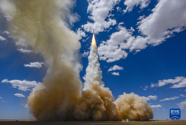
【Xinhua News】Successful launch of the Power Arrow 1 Remote 2 Launch Vehicle
-
 07 Jun,2023
【Real China through a Canadian Professor's Eyes】One-rocket, 26-star Rikyu-1 Remote 2 Launch Vehicle Launched Successfully
