The State Key Laboratory of Nonlinear Mechanics (LNM) was established in October 1999, the predecessor of which was the Open Laboratory for Nonlinear Mechanics in Continuum Media initiated in the Institute of Mechanics, Chinese Academy of Sciences (CAS) in 1988. LNM has the following characteristics: (1) promoting unique and original research; (2) emphasizing theoretical work that is validated by experiment; (3) strongly supporting free academic explorations. LNM lines up to be a world-class laboratory in nonlinear mechanics.
Steered by the strategic foresight of the state, LNM directs the fundamental problems of nonlinear mechanics. LNM focuses on the theoretical and applied research of nonlinear effects in solids, fluids, and their overlapping fields. LNM promotes and leads the development of nonlinear mechanics as an important base for high-level scientific research in mechanics worldwide.
In line with Qian Xuesen’s idea of “engineering science”, LNM has made significant academic achievements and technological breakthroughs meeting national strategic needs in the main battlefield of the national economy, such as the design and reliability of high-speed railroads, marine engineering, and new energy development.
LNM’s main achievements in nonlinear mechanics include four Second Prizes in Chinese State Natural Science: (1) thermo-plastic shear bands (1993); (2) micro-plasticity and micro-fracture of solids (2008); (3) microstructural mechanisms and size effects of mechanical behaviors of nanostructured metals (2013); and (4) shear bands in metallic materials with effects of inhomogeneous structures (2020).
Regarding the statistical theory and numerical simulations of turbulence, the major achievements are as follows: (1) the elliptic model for space-time correlations of turbulent shear flows; (2) the kinematic sub-grid scale model for unresolved scales in large-eddy simulation; and (3) the space-time correlation methodology for large-eddy simulations. These new models and methods have been widely applied in numerical simulations and the prediction of turbulence-generated noise and turbulent dispersion.
Along with the achievements in the discipline, a team of talent has been developed. LNM has been a national talent pool since it was founded. Prof. Zheng Zhemin (member of CAS, recipient of the State Top Scientific and Technological Award) pioneered the discipline of explosion mechanics. Prof. Bai Yilong (member of CAS) has made significant achievements in impact dynamics and thermo-plastic shear bands. Prof. Wang Ziqiang (member of CAS) has made great progress in fracture mechanics and strain-gradient theory. There are many other academic leaders with distinction in the discipline of solid mechanics, for example, three recipients of the National Science Fund for Distinguished Young Scholars; two recipients of the “100 Talent Program” of the CAS; two recipients of the New Century National Hundred, Thousand and Ten Thousand Talent Project; and three recipients of the National Science Fund for Outstanding Young Scholars. Besides outstanding leaders, the research teams are well-structured with faculty of different levels, career stages, and ages.
Unique Equipment:
Left Heart Simulation Platform
The left heart simulator is a pulsatile flow loop that is designed for modeling the hemodynamic conditions of the heart. This equipment can be used to explore the fluid dynamics within the heart and assess the performance of different types of heart valves and ventricular assist devices. This simulator contains components including the left atrium, mitral valve, left ventricle, aortic valve, and systemic compliance and resistance. A piston is driven to contract and relax the left ventricle, and the corresponding hemodynamic parameters such as pressure and flow are measured by high-precision transducers. The left heart simulator and data collection are controlled by an in-house program.
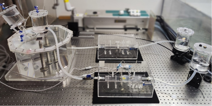
Figure 1. Left heart simulation platform.
Measurement and Analysis Facilities for Solid Mechanics in LNM
Studying the deformation, damage, and failure behaviors of solids is one of the long-term research orientations of LNM. To assist the study, corresponding experimental facilities have been constructed, including (1) equipment for microstructure characterization, (2) equipment for mechanical testing, and (3) equipment for specimen preparation. The length scale measured by the equipment ranges from 0.1 nm to 1 m. The measured force covers 14 orders of magnitude from nN to 200 kN. The loading strain rate spans 8 orders of magnitude from 10-5 s-1 to 103 s-1. The details of the three sets of equipment are as follows.
1. Microstructure characterization equipment
The microstructure characterization equipment is mainly used to measure and analyze the morphologies, microstructures, and physical properties of specimens. The microstructure characterization equipment includes optical microscopy (OM), scanning electron microscopy (SEM), transmission electron microscope (TEM), X-ray computed tomography system (CT), X-ray diffraction system (XRD), and differential scanning calorimeter (DSC), as partially illustrated in Figure 1. These instruments feature in-situ testing, which is the most important method for the mechanism study of solid mechanics. For example, the Zeiss Gemini300 SEM is configured with an energy-dispersive X-ray spectrometer (EDS), electron backscatter diffraction (EBSD), and Hysitron PI85 in-situ mechanical experiment platform. The JEOL 2100F high-resolution TEM is configured with Oxford X-maxN 80T EDS and Hysitron PI95 in-situ mechanical experiment platform. Both systems can be used for in-situ mechanical testing with a high spatial resolution (~nm). The Y. Modular CT system is configured with a self-developed 10 kN loading system, which is especially suitable for the study of the deformation and damage of composite materials.

Figure 1 Equipment for microstructure characterization.
2. Mechanical testing equipment
The mechanical testing equipment includes the micro/nano mechanical testing system, the quasi-static testing system, the fatigue testing system, and the high strain rate testing system. The micro/nano mechanical testing system includes two nanoindenters (Hysitron TI950 and Agilent G200) and one in-situ nanomechanical testing system (Veeco multimode pico-force TM, and Hysitron triboscope). These instruments are mainly used for hardness and modulus testing from nanometers to micrometers. The quasi-static testing system and fatigue testing system include material testing machines (MTS 809 250 kN, MTS landmark 50 kN, INSTRON E10k) and a very high-frequency fatigue system (GF20k). The material testing machines can provide a maximum load of 250 kN and a maximum load frequency of 30 Hz. The very high-frequency fatigue system can provide a fatigue frequency of 20 kHz, which is suitable for the study of very high-cycle fatigue. The high strain rate testing system includes a medium strain rate testing system (INSTRON VHS160/100-20), three self-developed split Hopkinson bar systems, and a self-developed one-stage light-gas cannon with an all-fiber photonic Doppler velocimeter (PDV). Some of them are shown in Figure 2.

Figure 2 Equipment for mechanical testing.
3. Specimen preparation equipment
In general, specimen preparation includes cutting from large-size materials, grinding, mechanical polishing or electropolishing, chemical corrosion, and heat treatment. In LNM, there are numerical control wire electric discharge machines for metal material cutting, automatic grinding and polishing machines, and muffle furnaces for heat treatment. These instruments cater to the general requirements for specimen preparation. Meanwhile, LNM is equipped with twin-jet electropolishing devices, dimple grinders, and precision ion polishing systems to prepare very thin foil specimens for TEM characterization. The most distinctive equipment for specimen preparation is the focused ion beam (FIB) with the model FEI Helios NanoLab G3 CX, which could be used to cut foil specimens from bulk materials at any site concerned. Please see the examples shown in Figure 3 below.
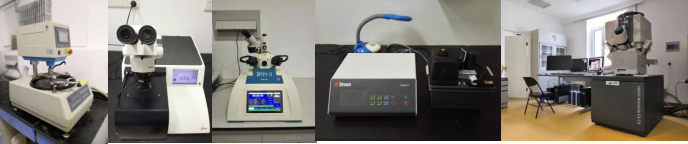
Figure 3 Equipment for specimen preparation.