- Home >> News >> Highlights
Highlights
The Overstretch Strategy-A New Strategy to Double Stretchability of Stretchable Electronics
Stretchable electronics have been extensively developed in the last decade for diverse applications ranging from health monitoring, medical treatment, and intelligent industries to aerospace equipment with stretchable or curvilinear characteristics. The key technological innovation in inorganic stretchable electronics is the achievement of elastic stretchability through the designed mechanical structures, enabling conformal wrapping on arbitrarily complicated target surfaces, maintaining the electronic functions unchanged. For instance, the “island-bridge” mesh structure, in which the functional components reside at the “islands” and the interconnects form the “bridges,” is the most popular one. The “islands” undergo negligible deformation during the stretch of the structure, and the “bridges” provide both elastic stretchability and electronic conductivity. Strategies for achieving elastic stretchability of stretchable electronics are critically essential and have attracted significant research attention.
Although several previous studies have focused on the design of stretchable structures, as shown in Figure 1, only two fundamental strategies have been exploited to achieve or enhance elastic stretchability. These strategies are described as follows. 1) By using the prestrained elastic substrate; a waved ribbon is a typical example. A pre-strain is applied to the elastic substrate before the straight planar ribbon is transfer-printed and bonded. The release of the prestrain yields compression and out-of-plane buckling of the transfer-printed ribbon, forming a waved shape with stretchable characteristics. Besides, more complex stretchable 3D meso-structures are fabricated by 2D precursors bonded to prestrained elastic substrates. 2) By designing geometric layouts; versatile stretchable structure layouts involving curved interconnects have been designed; these include horseshoe, serpentine, fractal, non-buckling, helical structures, and kirigami-inspired structures which exhibit different features in terms of elastic stretchability and application scenarios. Sometimes, the two types of strategies are combined to enhance the stretchability of mechanical structures. For instance, a prestrained elastic substrate significantly increases the stretchability of serpentine structures.
Recently, Yewang Su's team at the Institute of Mechanics, Chinese Academy of Sciences, innovatively proposed a third strategy to improve the elastic stretchability of stretchable electronics, i.e., an overstretch strategy (Figure 2). This study proposes overstretching beyond the designed elastic range of stretchable structures, applied after transfer printing and bonding to the soft substrate. The overstretch strategy can double the designed elastic stretchability, which is critical for the performance of stretchable electronics. The theoretical, numerical, and experimental results collectively prove that the overstretch strategy is valid for various geometrical interconnects with both thick and thin cross-sections (Figure 3, 4, 5). The underlying mechanism is revealed owing to the evolution of the elastoplastic constitutive relation of the critical part of the stretchable structures during overstretching. The overstretch strategy can be easily executed and combined with the other two strategies to enhance elastic stretchability, which has profound implications for the design, fabrication, and applications of stretchable electronics. The research results are published in the academic journal “Advanced Materials” under the title of “An Overstretch Strategy to Double the Designed Elastic Stretchability of Stretchable Electronics” (DOI: 10.1002/adma.202300340). The first author of the paper is Juyao Li, a PhD student at the Institute of Mechanics, Chinese Academy of Sciences, and the corresponding author is Yewang Su, a researcher at the Institute of Mechanics, Chinese Academy of Sciences, with the participation of Xiaolei Wu, a researcher at the Institute of Mechanics, Chinese Academy of Sciences, in the work. This work is supported by the National Natural Science Foundation of China, the 0 to 1 Original Innovation Program of the Chinese Academy of Sciences, CAS Interdisciplinary Innovation Team, and the WRQB Talent Program of the Chinese Ministry of Organization.
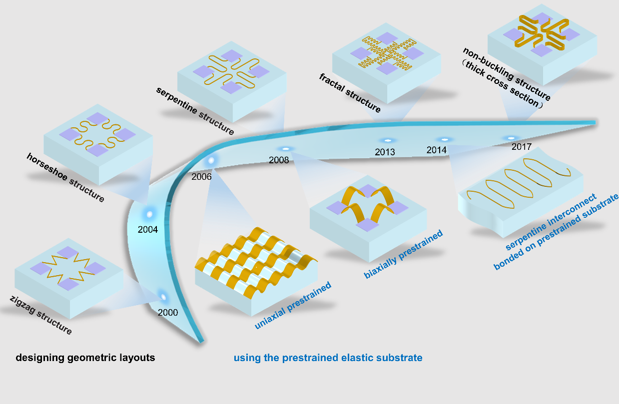
Figure 1. Evolution of stretchable structures over the past decades.
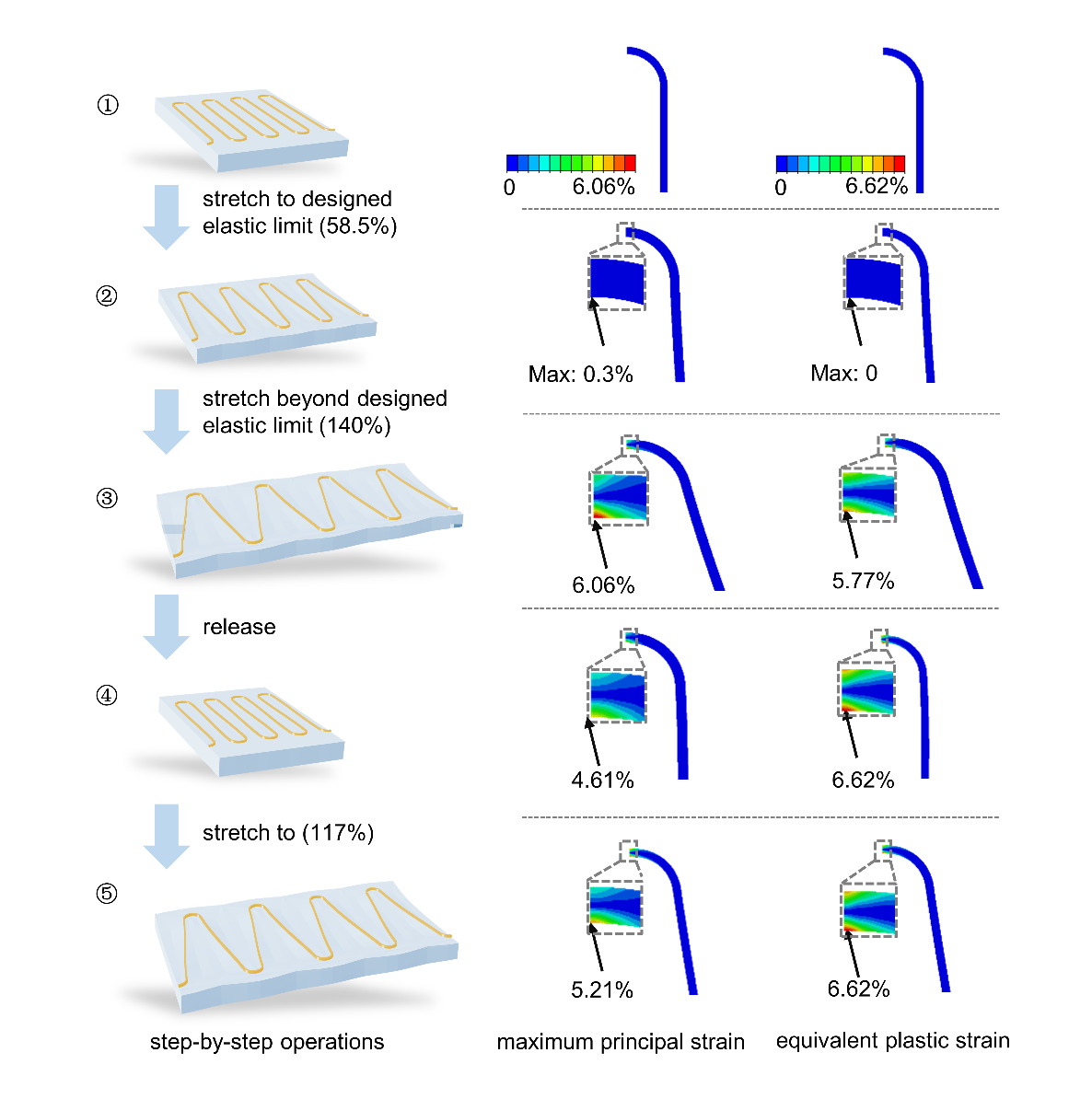
Figure 2. Operation of the overstretch strategy. The column on the left (Column 1) shows the step-by-step operation of the overstretch strategy: ①-② stretching to the designed elastic limit (58.5%), ②-③ stretching beyond the designed elastic limit (140%), ③-④ releasing the applied strain, ④-⑤ stretching to enhanced elastic limit (117%). Columns 2 and 3 provide the contours of the finite element analysis (FEA) for the maximum principal strain and equivalent plastic strain of the MTSI corresponding to each step in Column 1, respectively.
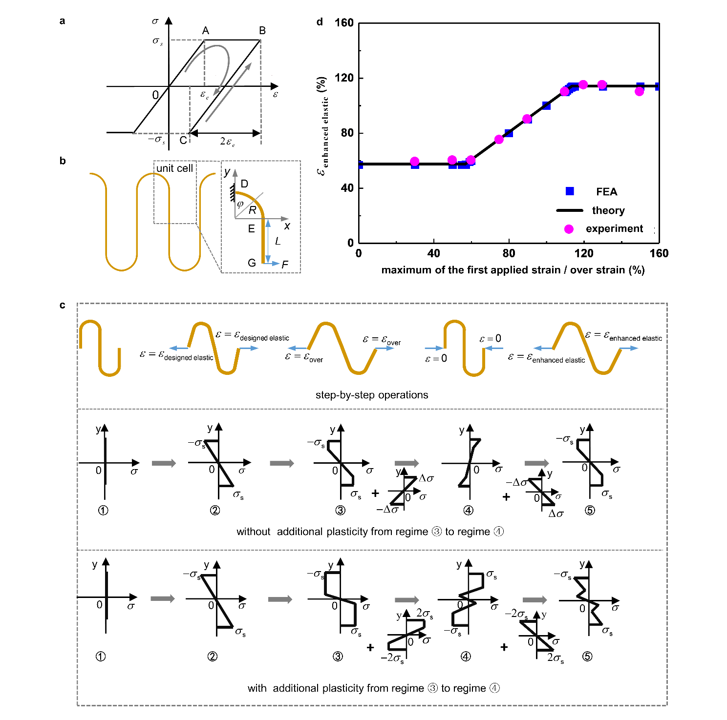
Figure 3. Mechanical analysis of the overstretch strategy via the freestanding MTSI. a Mechanical constitutive relationship of the MTSI: ideal elastoplasticity. b Schematic and mechanical model of the freestanding MTSI. cFirst row: step-by-step overstretch strategy operation with freestanding MTSI (one period). Second row: stress distribution in the cross-section of the semicircle vertex in each process if no additional plasticity occurs from regime③ to ④. Third row: stress distribution in the semicircle vertex cross-section in each process if additional plasticity occurs from regime ③ to ④. d Enhanced elastic stretchability of the freestanding MTSI as a function of the maximum of the first applied strain / over-strain, including the results of the experiments, FEA, and theory.
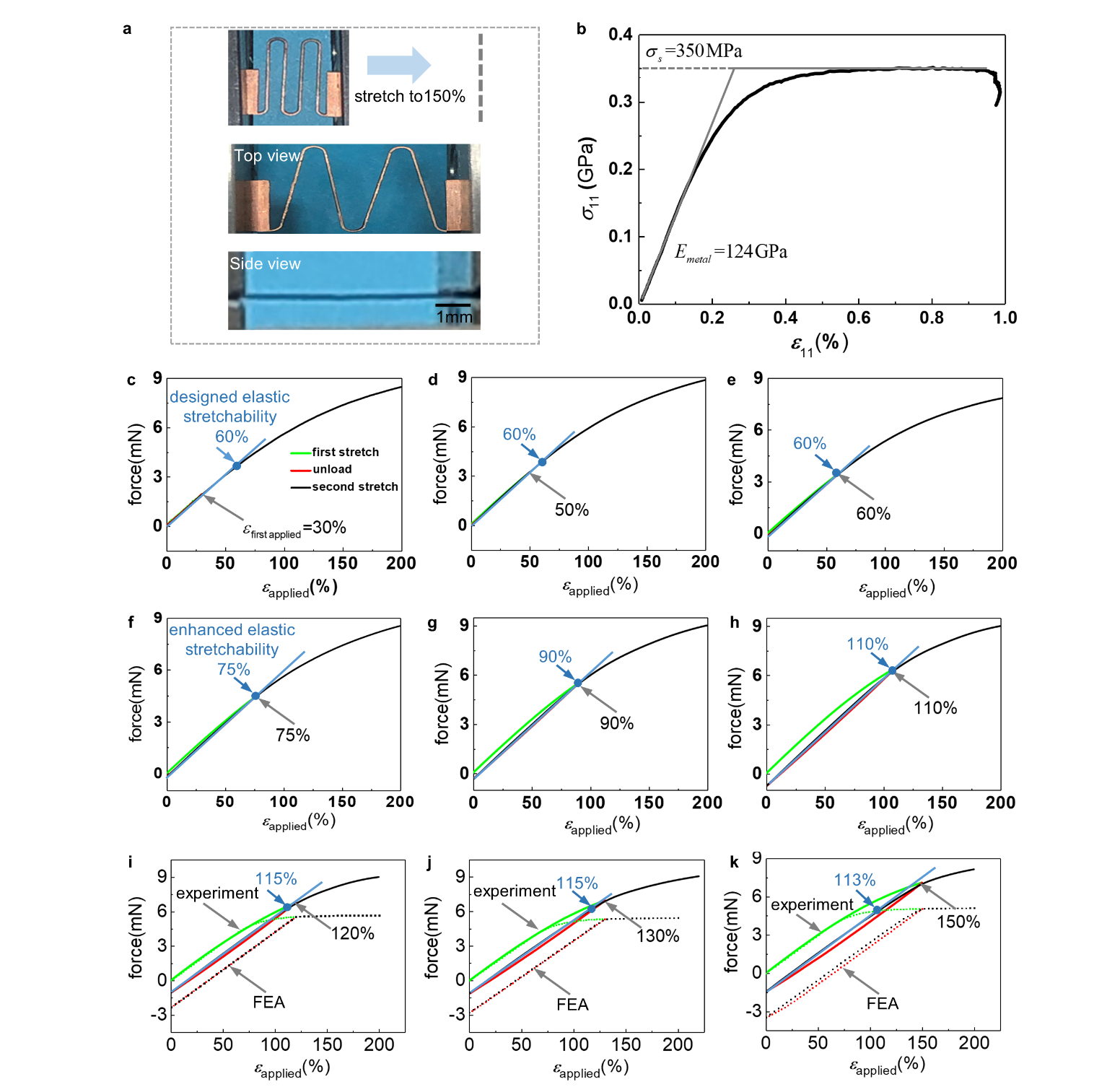
Figure 4. Experimental verification of the overstretch strategy via the freestanding MTSI . a Images of the initial state of the freestanding MTSI and the front and side views when stretched by 150% (from top to bottom). b Stress–strain curves of a dog-bone-shaped copper plate in uniaxial tension. c-k Curves of the force versus the applied strain during the first applied stretch, unloading, and second applied stretch; the first applied strain for c–k is 30%, 50%, 60%, 75%, 90%, 110%, 120%, 130%, and 150%, respectively (i-k contain the FEA results, dotted lines).
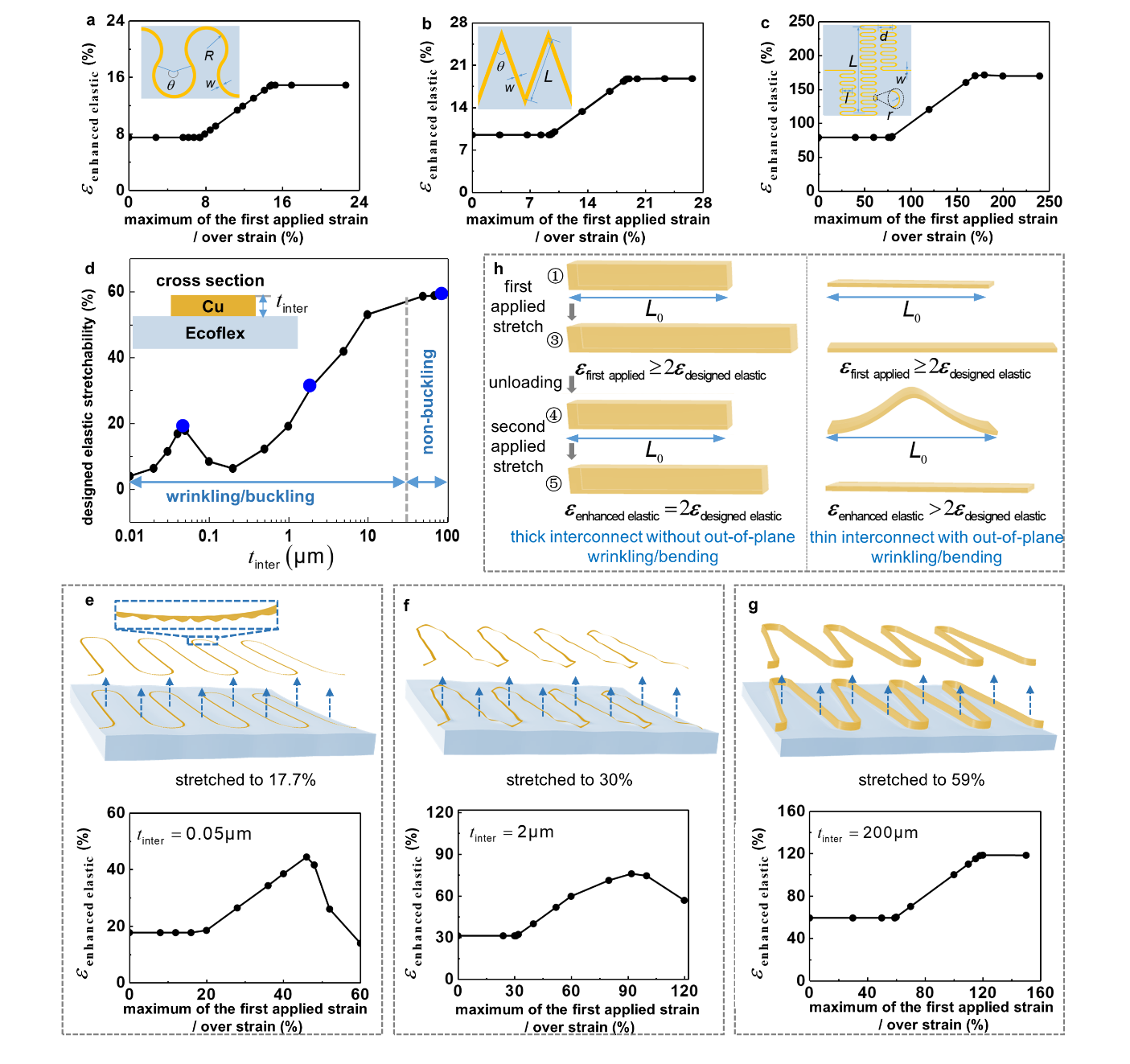
Figure 5. Mechanical analysis of the MTSI bonded on the soft substrate. a/b/c Enhanced elastic stretchability of thick horseshoe/zigzag/fractal interconnects bonded on the soft substrate as a function of the maximum of the first applied strain / over-strain. d Curve of the designed elastic stretchability of serpentine interconnection bonded on the soft substrate as a function of its thickness. e-g FEA results of serpentine interconnections with three typical thicknesses . The upper subgraphs are the corresponding wrinkling, buckling, and non-buckling deformation during stretching, and the lower subgraphs show the relationship between the enhanced elastic stretchability of the structure and the maximum of the first applied strain / over-strain. h Schematic of the deformation modes of the partial semicircle for the thick and thin interconnects.
Original link: An Overstretch Strategy to Double the Designed Elastic Stretchability of Stretchable Electronics (wiley.com)